
What Determines Capacitive Voltage Transformer Measurement Accuracy?
2026-11-12 17:21:55
A capacitive voltage transformer is accurate when its capacitor divider, compensation reactor, intermediate transformer, and connected burden work as one tuned system. Capacitor stability sets the voltage ratio. Reactor tuning controls phase displacement. Secondary burden, frequency, temperature, insulation condition, grounding, and installation quality can then push the result off target. A nameplate voltage tells you very little about real performance. In this guide, I explain each factor in plain terms, show how engineers verify accuracy, and list what to check before you buy a 69/72.5 kV unit for a substation project.
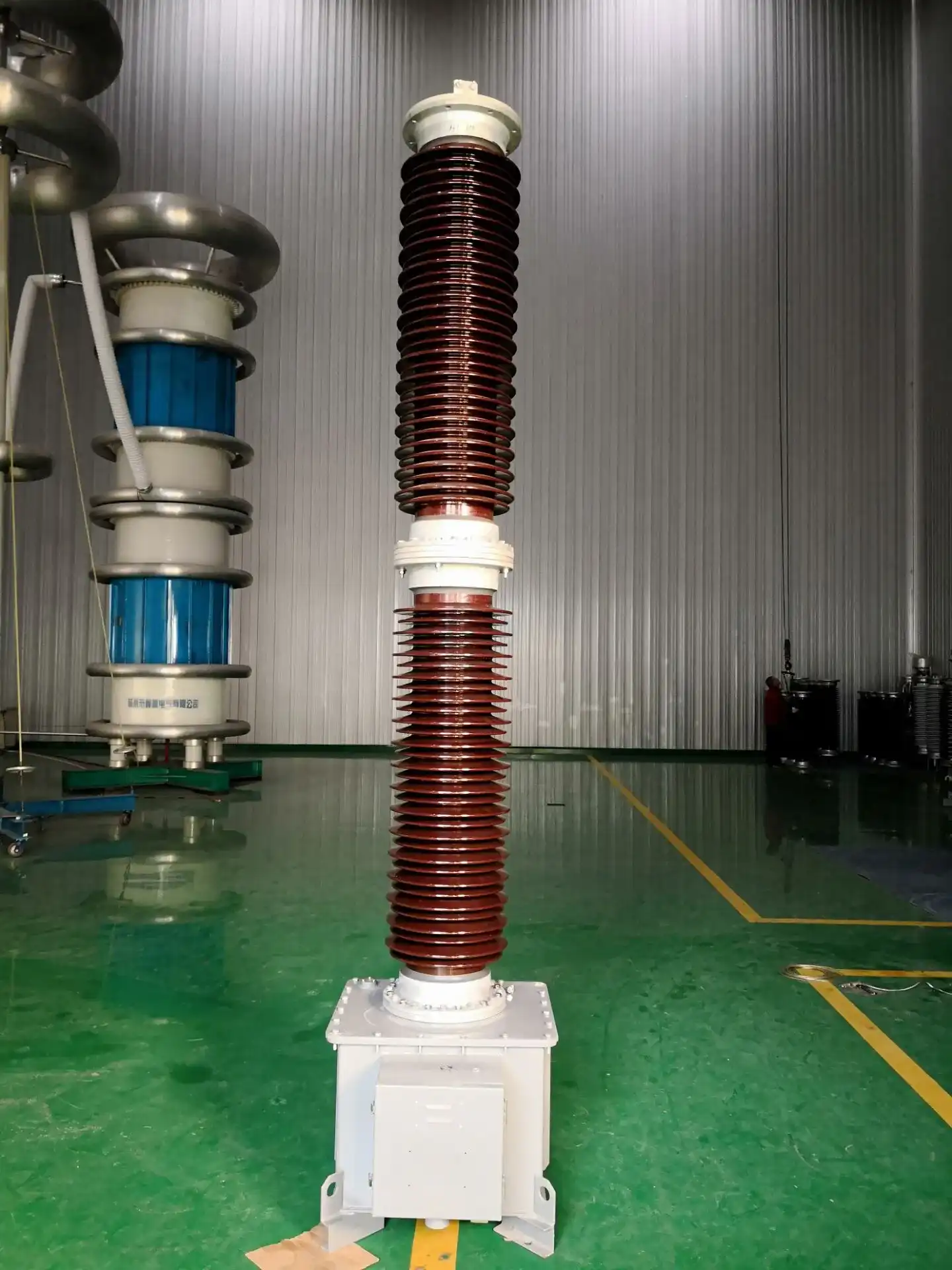
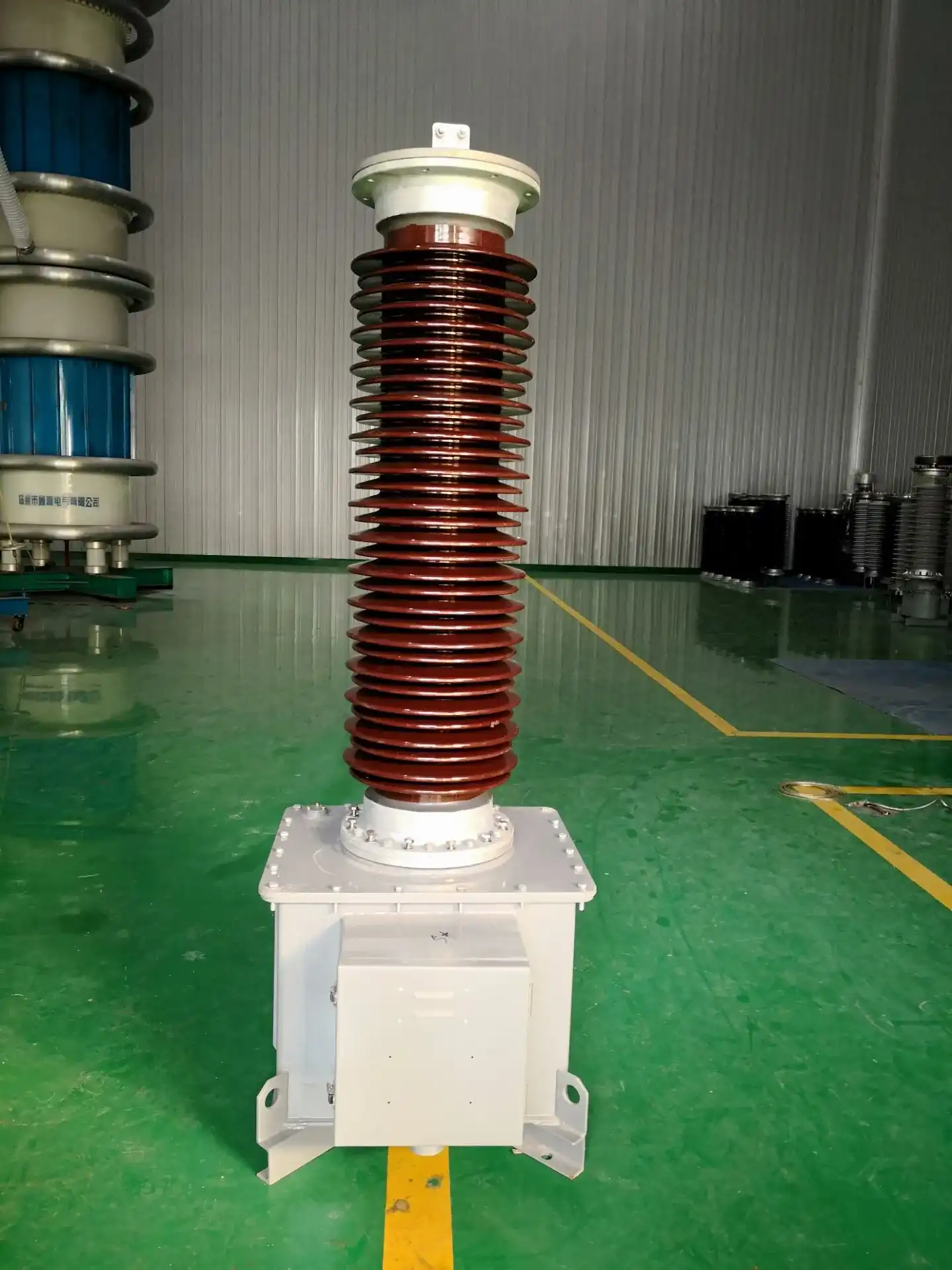
What Is a Capacitive Voltage Transformer and How Does It Work?
Why Accuracy Matters in a 69 kV Substation
It changes a high system voltage into a normal low-voltage secondary signal. This is done by a capacitive voltage transformer, or CVT. That signal can be read by meters, relays, devices that sync up devices, and problem records. Ratio error and phase displacement are the two numbers that show how accurate something is. Both need to be limited a lot for revenue metering to work. Protection relays are more interested in how the signal acts when there is a fault. At 69 kV, a small mistake in the ratio can mess up billing information, and an error in the phase can mess up estimates for power. So, I think you should check the accuracy class before checking any other information.
How the Capacitive Voltage Transformer Reduces Voltage
When there is only one wire on the capacitive voltage transformer, the line voltage does not drop. The primary voltage is split into two parts by a stack of series capacitors, which creates an intermediate voltage. At power frequency, a compensation reactor then gets rid of the divider's capacitive reactance. Last but not least, an intermediate transformer lowers the voltage once more and supplies power to the windings for measuring and protecting. Builders think of these parts as a single circuit because they work with each other. The high-voltage terminal, capacitor parts, reactor, intermediate transformer, secondary outputs, and ground should all be shown on a simple figure. A lot of designs can also communicate over power lines.
Which Standards Set the Accuracy Limits
Standards say how to test and state correctness. An American standard called IEEE C57.13 talks about instrument transformers and has a list of measuring accuracy classes, such as 0.3, 0.6, and 1.2, for standard loads called W, X, M, Y, Z, and ZZ. IEEE C93.1 talks about linking capacitive voltage transformers that are connected to a power line carrier. IEC 61869-5 adds requirements for capacitor voltage transformers, such as classes for transient response. Each system has its own set of class names and test conditions, so you can't switch between them. On your project, each capacitive voltage transformer should say what standard it works with. Let us know early on if you need IEEE or ANSI documentation so we can look it over with you.
What Are the Main Factors That Determine CVT Measurement Accuracy?
Capacitor Stability and the Divider Ratio
The capacitance of the upper and lower sections tells us the divider ratio. Rate of change moves along with changes in capacitance. Capacitance can change over time because of things like moisture, broken seals, dielectric aging, and changes in temperature. A tight tolerance at the factory is helpful, but for a capacitive voltage transformer that will be in a substation for decades, long-term stability is more important. Another sign is dielectric loss. Low dielectric loss means less burning inside and less change over time. Before I look at a datasheet, I check to see if it has measurements for capacitance, dielectric loss, and the method used for sealing.
Reactor Tuning and the Intermediate Transformer
The compensation reactor is tuned so that the circuit resonates at the frequency that was set. The phase shift and ratio mistake get worse if the system frequency changes or the tuning is off. Because it has its own magnetizing current and wound resistance, the intermediate transformer makes its own small mistakes. When the voltage range is set, a good design keeps these effects in the accuracy class. Also, make sure the tuning is correct before connecting a capacitive voltage transformer made for 60 Hz to a 50 Hz grid. The frequency range for our 69 72.5kV capacitive voltage transformer is 50 Hz to 60 Hz. You should make sure that the tuning frequency is correct when you place your order.
Burden, Temperature, and Environment
Outside of the unit, three things often cause the result to be different from the factory license.
- Secondary burden: The secondary winding is used to power things like meters, switches, long control lines, and communication devices. Ratio error and phase displacement go up when the total linked load is higher than the rated number. Instead of relying on a rough guess from the design plans, check the real load at the secondary terminals, taking into account the resistance of the wire.
- Temperature and altitude: Capacitance and shielding change as the temperature changes, and when you go up in elevation, the air is thinner, which lowers the external dielectric strength. Write down the site's temperature range and height in the specification. Our 69 72.5kV capacitive voltage transformer can work in temperatures ranging from -40°C to +55°C, so it can be used in substations that are cold in the winter and hot in the summer.
- Pollution and moisture: Dust, salt, and factory fumes cover the insulator and make a conductive film on it. Then, leakage current can change how the voltage is spread across the capacitor stack, which can lead to flashover. Most of the defense comes from creeping distance. For marine and industrial places, our unit has 35 mm/kV and longer silicone rubber skirts.
Checking these three items before you order helps you avoid most accuracy problems found at commissioning.
Why Two CVTs with the Same Rated Voltage Can Differ
It is possible for two capacitive voltage transformers with the same 69 kV rating to read differently when they are in use. If you pull a heavy load along a long cable run, its ratio error will go up. One might have old capacitor parts whose capacitance has changed. Three of them can be tuned for fundamental-frequency measurement but used for harmonic studies, since CVT frequency response limits what they can do. None of this is shown on the nameplate. I never just look at the voltage rating when I compare things; I also look at the divider, reactor, load, wiring, environment, and test history.
How Does CVT Accuracy Compare with Inductive Voltage Transformers?
Voltage Level and Application Fit
Both inductive voltage transformers and capacitive voltage transformers are used to measure voltage and keep things safe. When you use an inductive unit, the main is wound, and the broad and transient behavior is usually better. Since CVTs are more cost-effective as system voltage goes up, you can find a lot of them at 110 kV, 220 kV, and higher. Both types are used around 69 kV, and the project determines which one is best. A CVT works well when you need to connect to the power line and couple to a carrier, or when the power company already uses capacitor-type units all the time. Make sure you know the utility standard before making a choice.
Transient Response and Fast Relays
The batteries and generator of a CVT store energy. When there is a fault and the line voltage drops, the stored energy can leave a voltage on the secondary for a short time. Designers add damping circuits to reduce that signal so that fast distance relays don't get it wrong. IEC 61869-5 gives transitional performance grades with groups like 3PT1. Our 69 72.5kV fast relay requirements are met by a capacitive voltage transformer with a damping design that reaches the 3PT1 level with residual voltage below 2%. If you want to get accurate data in a steady state, you should ask any supplier for transient test reports as well.
Ferroresonance and Frequency Behavior
In a capacitive voltage transformer, the reactor and capacitors make up a circuit that can go into ferroresonance, which is a steady oscillation, after switching events. On the secondary of most CVTs, there is a reduction circuit that engineers should make sure works when it's really needed. Also, frequency reaction is important. A CVT is accurate close to its rated frequency, but it might not show harmonics or high-frequency content correctly. If your site has large drives or inverter-based generation, check to see if a CVT can be used to measure the power quality. Something else might be better for that job.
How Should Engineers Verify and Maintain CVT Accuracy?
Factory Acceptance Testing
This is the first proof that the factory tests were correct. Tests that are done regularly usually check for ratio error, phase displacement, divider capacitance and dissipation factor, insulation withstand, and partial discharge when needed. Engineers match each answer to the level of accuracy written on the order. With precision ratio and phase-angle test sets and reference voltage transformers, the measurements can be tracked. When they leave the plant, each capacitive voltage transformer should have its own record of tests. Our factories are ISO 9001-certified, and the capacitor elements we use are vacuum-impregnated. In our quality plan, we list tests for harmonic distortion, temperature cycling, and impulse voltage.
Site Acceptance Testing
It's possible for site checks to find bugs that factory tests miss. Check the polarity, phase sequence, ground connections, terminal tightness, and insulation condition of the capacitive voltage transformer after it has been installed. Then, check the real load on the secondary terminals, since the design drawing doesn't always match the cable length or relay choice. When you compare ratio and phase to a reference unit, you can be sure that they are within the acceptable range. Check the measurement and safety windings to make sure they are feeding the right devices, and test the ferroresonance suppression circuit as well. Every number should be written down as a starting point so that you can later compare trends.
Maintenance and Lifecycle Checks
Since accuracy can change over time, check it every so often. Oil leaks, cracked insulators, corrosion, and loose grounds should all be looked for visually. Before ratio error can be seen, capacitance and dissipation-factor tests on the divider show that it has been wet or has lost its dielectric properties. Every time someone adds a relay or meter, check the load again. Compare each reading to the starting point for the commissioning because the trend tells you more than a single reading. Our 69 72.5kV capacitive voltage transformer is made to last 25 years, and regular upkeep helps keep that promise.
What Should Buyers Review Before Procurement?
Specification Checklist
Most disagreements can be avoided by making the requirements for a capacitive voltage transformer very clear. It should have the rated voltage, the highest system voltage, the frequency, the insulation level, the voltage factor, the creepage distance, the secondary voltage, the number of windings, the rated burden, the metering and protection classes, and the transient class. Include details about the place, like the amount of pollution, temperature, height, seismic needs, size, and transport boundaries. Ask the seller for pictures, circuit diagrams, reports on type tests and routine tests, records of calibration, instructions, and the terms of the warranty. For US projects, make it clear whether the order is based on IEEE C57.13 or another standard. This way, everyone can use the same file.
Features of Our 69 72.5kV Capacitive Voltage Transformer
With our 69 72.5kV capacitive voltage transformer for 69 kV to 72.5 kV networks, you can do the following.
- High electric strength and insulation margin: With a new structure design and cutting edge technology, the unit is stronger against electricity and has a wider insulation margin. The mechanical strength of the capacitor insulator is very high, and the form of the framework makes the whole product even stronger. A small amount of dielectric loss helps keep the capacitance fixed over time.
- Accuracy and outputs: There are two levels of accuracy, 0.2 and 0.5. The tighter level of accuracy (±0.2%) is used for counting and security. With a dual-output setup, one unit can power both metering devices and safety switches. You can add optional IoT sensors that work with SCADA/EMS and allow for real-time diagnostics.
- Transient response and housing: The design of the damping gets to the 3PT1 level with less than 2% residual voltage, which works well for fast relays. Long creepage distance (35 mm/kV), long silicone rubber skirts, and an IP66-rated aluminum alloy housing protect against dust and water in harsh environments.
How to Choose a Capacitive Voltage Transformer Supplier
Before you ask for quotes, you should describe the job: the voltage, frequency, accuracy class, load, secondary setup, installation type, environment, standards, number, and destination. Not just price, but also technical value should be used to judge suppliers. Look for experience making things with high voltage, resources for testing, high-quality documents, help with customization, delivery, a warranty, and service after the sale. If this is your first IEEE or ANSI project, ask the supplier to show you how its test documentation fits with the standard you need. Xi'an Xikai uses patented technologies to make instrument transformers that work with a wide range of middle and low voltages. We look over drawings and send out technical quotes that are specific to the project.

Conclusion
The accuracy of the capacitive voltage transformer depends on the entire system, not just the stated voltage. The division ratio is set by stable capacitors. Phase shift is controlled by a reactor and an intermediate transformer that are properly tuned. Temperature, pollution, frequency, and secondary burden can all change the results from what the factory set them to. CVTs are cheaper at higher voltages than inductive voltage transformers, but you need to pay attention to their transient response, ferroresonance, and frequency behavior. Errors can be seen thanks to baseline records, testing at the factory and on-site, and regular checks of capacitance and burden. It's easier for buyers to compare products when there is a clear specification that lists the governing standard, accuracy class, burden, environment, and transient class. This makes it easier to set up and replace products.
FAQ
1. What causes capacitive voltage transformer accuracy drift?
Many times, it's because the divider's capacitance changed. It happens because of moisture, old age, or a broken seal. Adding a secondary load over time also makes a difference.
2. Can one winding serve both metering and protection?
It can, but each class and load are kept clear by their own separate windings. Our unit has two outputs, one for metering and one for protection relays.
3. How often should I test a CVT?
During commissioning, take baseline readings. Then, follow the rules set by your utility company. A load check should be done after any relay or meter change, and capacitance and dissipation-factor tests are common.
4. What should I send for a quotation?
Include the voltage, frequency, load, number of windings, installation environment, governing standard, quantity, and delivery location in the message.
Request a Capacitive Voltage Transformer Quote from Xi'an Xikai
The Xi'an Xikai company can look over your 69/72.5 kV requirements and suggest a suitable capacitive voltage transformer. We are a capacitive voltage transformer maker with patented technologies and ISO 9001-certified production. We offer drawing reviews, test documents, and customizations that are made just for your project. Email serina@xaxd-electric.com, amber@xaxd-electric.com, or luna@xaxd-electric.com with your voltage, accuracy class, load, location, and standard. If you want to know more, go to xaxd-electric.com.

References
1. IEEE Std C57.13, IEEE Standard Requirements for Instrument Transformers, 2016
2. IEC 61869-5, Instrument Transformers – Part 5: Additional Requirements for Capacitor Voltage Transformers, 2011
3. IEC 61869-1, Instrument Transformers – Part 1: General Requirements, 2007
4. IEEE Std C93.1, IEEE Standard Requirements for Power-Line Carrier Coupling Capacitors and Coupling Capacitor Voltage Transformers (CCVT), 1999
5. Protective Relaying: Principles and Applications, 2014
6. Electric Power Substations Engineering, 2012