
_1794379697699.jpg)
_1794379700480.jpg)

-square BKMJ_1758505876091.webp)
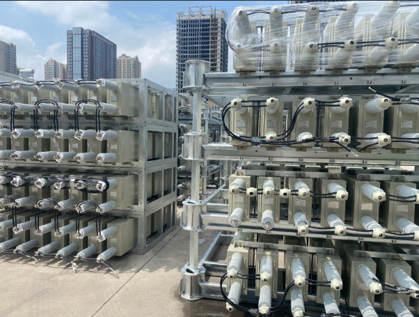
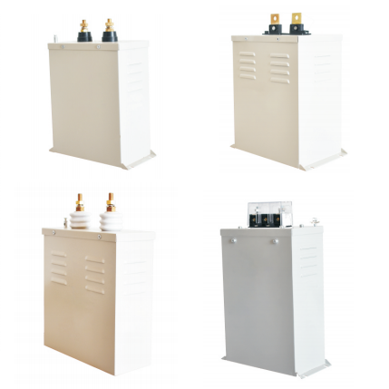
50KVAR Self-healing Capacitor for PFC(Power factor correction)-square BKMJ
capacitor in parallel with resistor
1.Rated Voltage:6kV,10kV,35kV.
2.Rated Capacity:1-100Mvar(per bank).
3.The capacitor is mainly consisted of container and device body.
4.The core is consisted of severalelements and insulation parts. The element is rolled, pressed andmade of two aluminum foilsand somepiece of thin dielectric polypropylene films sandwiched betweenthe two aluminum foils. In order to reach the differentdemand of voltage and capacity, the elements in core is connected by someseriesand parallelmethod. The technology of aluminum foiledge folding and protruding weldingare used to reduce the loss and increase the performance of partial discharging.
2.Rated Capacity:1-100Mvar(per bank).
3.The capacitor is mainly consisted of container and device body.
4.The core is consisted of severalelements and insulation parts. The element is rolled, pressed andmade of two aluminum foilsand somepiece of thin dielectric polypropylene films sandwiched betweenthe two aluminum foils. In order to reach the differentdemand of voltage and capacity, the elements in core is connected by someseriesand parallelmethod. The technology of aluminum foiledge folding and protruding weldingare used to reduce the loss and increase the performance of partial discharging.
- Fast Delievery
- Quality Assurance
- 24/7 Customer Service
Product Introduction
Capacitor in Parallel with Resistor - Professional Solutions for Power Distribution
When you need reliable voltage management and energy dissipation in electrical systems, a capacitor in parallel with resistor configuration offers the perfect solution. This fundamental circuit topology combines energy storage capabilities with controlled current dissipation, making it essential for modern power distribution applications. At Xi'an Xidian Medium and Low Voltage Electric Co., Ltd., we understand that your electrical systems demand both safety and performance. Our parallel RC circuits provide superior frequency response characteristics while maintaining excellent voltage dynamics for your critical applications.
Technical Specifications
| Parameter | Specification | Unit |
|---|---|---|
| Rated Voltage | 0.4kV - 40.5kV | kV |
| Rated Current | 630A - 4000A | A |
| Capacitor Voltage Range | 6kV, 10kV, 35kV | kV |
| Rated Capacity | 1-100 Mvar | Mvar |
| Operating Temperature | -40°C to +85°C | °C |
| Altitude Rating | Up to 4000m | meters |
| Discharge Time Constant | Customizable (τ = R × C) | seconds |
| Power Rating | 1kW - 50kW | kW |
| Frequency Range | 50Hz - 60Hz | Hz |
Main Features and Advantages
Superior Safety Performance
Our parallel RC circuits include built-in bleeding resistors that safely discharge capacitors when power is removed. This feature ensures compliance with international safety standards and protects your personnel from electrical hazards.
Enhanced Frequency Response
The configuration provides excellent AC signal bypassing while maintaining DC bias stability. You get optimal voltage gain for your desired frequencies without compromising your system's operating point.
Robust Construction
Each unit features aluminum foil elements with polypropylene film dielectric, ensuring long-term reliability. The edge folding and protruding welding technology reduces losses and improves partial discharge performance.
Customizable Solutions
We design each system to meet your specific voltage and capacity requirements using series and parallel element connections. This flexibility ensures perfect integration with your existing infrastructure.
Practical Applications
Industrial Power Distribution
Your heavy-duty inverters and variable frequency drives benefit from our DC link bank configurations. The parallel resistors act as bleeder circuits while large electrolytic capacitors maintain smooth DC rails for 24/7 industrial operations.
Signal Processing Systems
In analog amplifier applications, our bypass capacitors in parallel with emitter resistors significantly increase voltage gain. This setup is crucial for high-fidelity audio equipment and RF signal processing chains.
Automotive Electronics
Modern vehicle ECUs require noise filtering for sensor inputs. Our capacitor in parallel with resistor configurations filter RF interference and stabilize voltage readings in harsh electromagnetic environments.
Power Factor Correction
Large-scale electrical installations use our parallel RC circuits to manage reactive power and improve overall system efficiency.
How It Works
The parallel configuration creates dual-path current flow with distinct frequency-dependent characteristics. At DC frequencies, the capacitor blocks current flow, making the total impedance equal to the resistance value. As frequency increases, the capacitor's reactance decreases, creating a low-impedance path for AC signals.
The discharge time constant (τ = R × C) governs energy dissipation rates. This relationship allows precise control over voltage decay characteristics, essential for safety applications and transient response management.
Phase relationships between current and voltage vary from 0° to 90°, depending on frequency and component values. This characteristic makes the configuration valuable for power factor correction and signal processing applications.
Manufacturing Excellence
Our production facility maintains strict quality control throughout the manufacturing process. We use advanced aluminum foil processing techniques combined with high-grade polypropylene dielectrics to ensure superior performance.
Each component undergoes rigorous testing including:
- Load life stability testing at elevated temperatures
- Dielectric withstanding voltage verification
- Thermal shock resistance evaluation
- Insulation resistance measurement
Quality certifications include ISO9001, ISO14001, and OHSAS18001, ensuring consistent product reliability and environmental compliance.
Why Choose Us
With over 100 product varieties across 34 series, we offer comprehensive solutions for your power distribution needs. Our engineering team provides expert technical support from initial design through installation and commissioning.
Proven Track Record
Our products meet all national and industry standards while maintaining domestic and international advanced performance levels. Recognition as a famous brand product in China demonstrates our commitment to excellence.
Complete System Integration
Beyond individual components, we provide complete system solutions including switchgear, transformers, and protection devices. This integrated approach ensures optimal compatibility and performance.
Technical Innovation
Continuous investment in research and development keeps our products at the forefront of technology. Our engineering team stays current with industry trends and customer requirements.
FAQ
Q: How do I select the right discharge time for safety applications?
A: Use the formula t = -R × C × ln(V_safe / V_initial). Most safety standards require voltage to drop below 60V within 2 seconds. We'll help calculate the optimal resistor value for your specific requirements.
Q: Will the parallel configuration affect my circuit's total resistance?
A: For DC analysis, the capacitor acts as an open circuit, so total resistance equals the resistor value. In AC applications, impedance decreases with frequency as the capacitor provides an alternative current path.
Q: What causes parallel resistor failures in these circuits?
A: Common issues include exceeding power ratings or working voltage limits. Even when capacitors handle AC ripple correctly, resistors must withstand full DC voltage and pulse loads during discharge events.
Q: Can I use standard capacitors for signal bypassing applications?
A: Signal processing requires low-ESR capacitors to ensure sufficient AC impedance reduction. High leakage current types should be avoided as they disrupt DC bias established by the parallel resistor.
Contact Us
Ready to optimize your power distribution system with professional capacitor in parallel with resistor solutions? Our technical team is standing by to discuss your specific requirements and provide customized recommendations.
Get Expert Consultation Today
Email: serina@xaxd-electric.com
Let us help you achieve superior electrical performance with our proven parallel RC circuit technologies.
Send Inquiry

_1776665574080.png)
_1794378776624.jpg)