
How to Evaluate Capacitive Voltage Transformer Performance
2026-11-13 17:20:25
To evaluate capacitive voltage transformer performance, check five items in order: accuracy class and phase displacement under the real burden, transient response after faults, insulation and creepage strength, long-term capacitor stability, and factory and site test evidence. A capacitive voltage transformer steps line voltage down for meters, relays, and carrier equipment, so small errors can distort billing data or delay protection. For 69/72.5 kV substations, add one more step: confirm that the supplier can document your required standard, whether IEEE/ANSI or IEC. We wrote this guide to help engineers and EPC project managers compare units on facts, not catalogue claims.
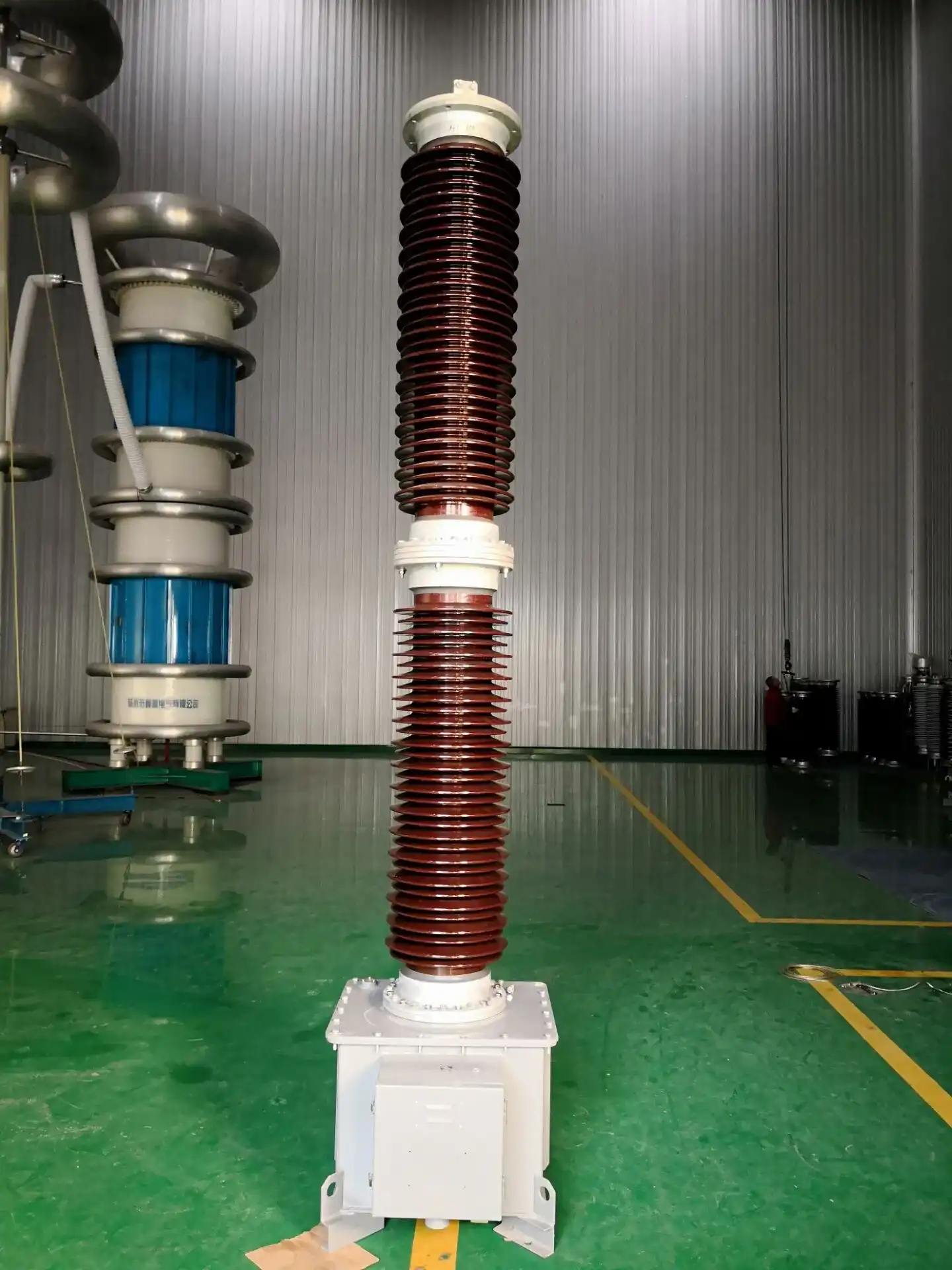
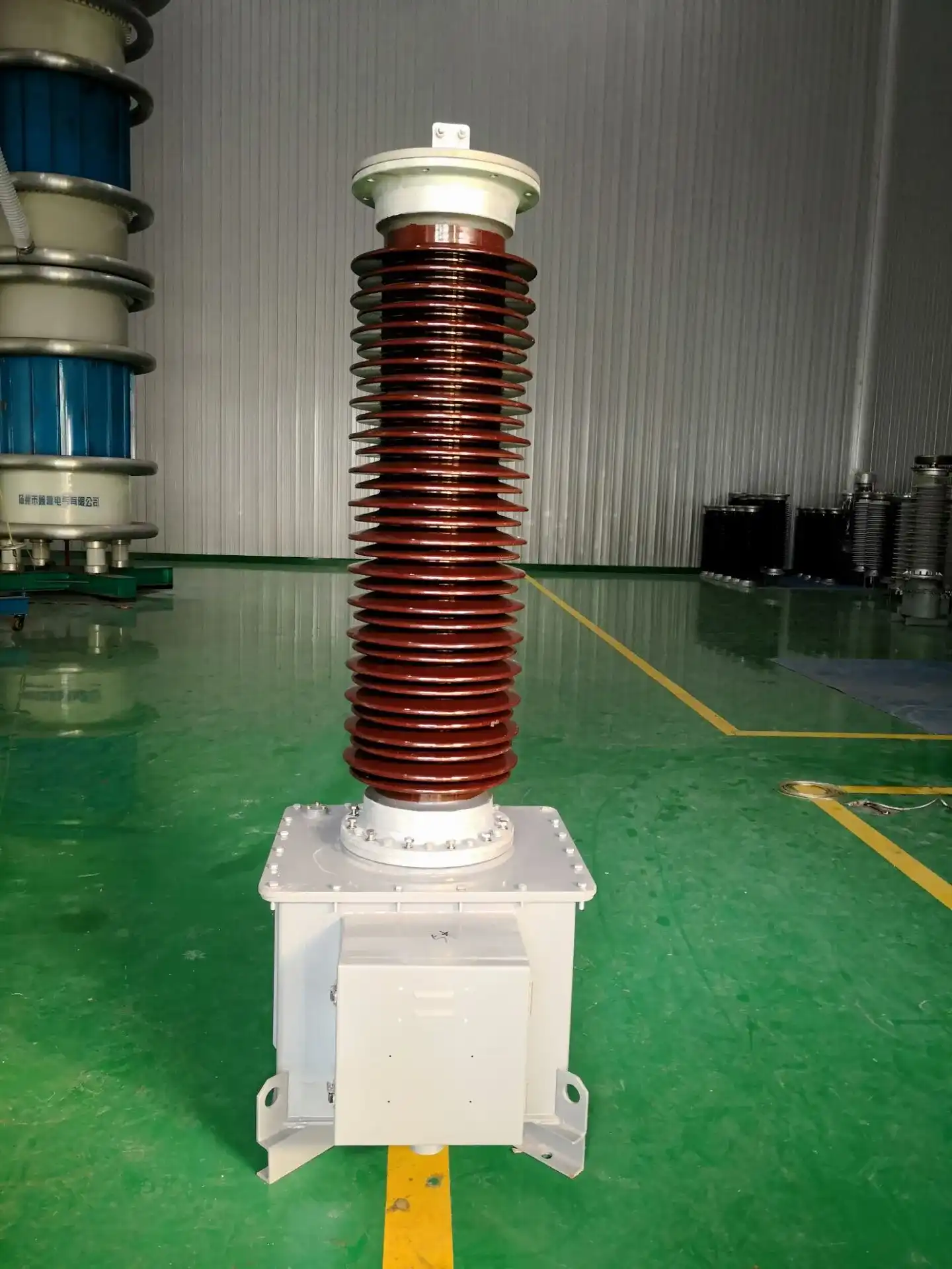
What Is a Capacitive Voltage Transformer and Why Does Performance Matter?
Role in a 69/72.5 kV Substation
A capacitive voltage transformer (CVT) lowers the transmission voltage to a normal secondary level with the help of a capacitor divider and a small electromagnetic unit. This signal powers revenue meters, safety switches, control systems, and synchronizing gear. When asked, it can also connect power-line carrier signals. In a 69/72.5 kV substation, 69 kV is the standard system voltage in North America, and 72.5 kV is the highest voltage an IEC piece of equipment can handle. They often work together on the same project: the design office writes the IEEE rules, and the supplier tests to the IEC standards. Performance evaluation checks to see if one connected device can do all the tasks correctly.
Why Performance Gaps Cost More Than the Unit Price
If there is even a small mistake in a capacitive voltage transformer, it affects everything that reads its signal. The energy data used for billing is off because of a ratio error. When there is a fault, a relay may not trip right away if the fleeting reaction is slow. Outages that cost a lot more than the instrument itself can be caused by insulation that isn't strong enough. For an EPC provider, one failed acceptance test can also cause the project plan to be thrown off and delay the start of work. So, I think you should give each candidate a score based on their accuracy, transient behavior, insulation, documentation, and service support, with price being one of the factors you consider.
Which Standard Backs the Claim
Start with the level of quality that your job needs. Metering accuracy classes in IEEE Std C57.13 are 0.3, 0.6, and 1.2. These classes are tested at standard loads of 90% to 110% of rated voltage. The connected load is shown by burden designations like W, X, M, Y, Z, and ZZ. There are more rules for capacitor voltage transformers in IEC 61869-5, and IEEE Std C93.1 talks about how to connect capacitive voltage transformers to carrier equipment. There are different class labels and test methods for these documents, so a certificate for one won't work for the other. Ask each supplier to back up every claim with a standard, edition, and test lab.
Understand the Capacitive Voltage Transformer Working Principle and Construction
How the Divider and Reactor Work Together
The capacitor stack in a capacitive voltage transformer splits the line voltage into a smaller intermediate voltage. At power frequency, a compensating reactor cancels out the divider's capacitive reactance. This keeps the output steady when the load is on it. The secondary signal is then sent by an electromagnetic transformer that is fed by the intermediate voltage. When the load changes, the output of a capacitor divider can drift because its source impedance is high. This is why the compensation circuit needs to closely match the divider. Ask for a circuit diagram with labels. Plus, you can see the signal path from the main terminal to each secondary winding and make sure that the metering and protection windings are separate.
Key Components That Shape Accuracy
The measured performance of a capacitive voltage transformer is affected by every part of it. The tolerance and temperature behavior of the capacitor elements determine how stable the system will be over time. Phase shift is affected by the reactor and the electromagnetic unit. Transient oscillation and ferroresonance are controlled by a damping circuit. The external insulation strength is set by the insulator and its skirts. The secondary connections are made in the terminal box. Ask for an outline of these parts and the way that capacitor elements are inspected when they come in. Find out if each capacitor element is checked for its own capacitance. If a manufacturer keeps track of parts by lot, they can find where a problem in the field came from.
Why Component Matching Matters
If you change one part, it can affect the ratio error, resonance behavior, and frequency response. This is because the tolerance of the capacitor, the qualities of the reactor, and the damping factors all work together. It changes with weather and age, too, which makes the divider ratio change slowly. For 69/72.5 kV capacitive voltage transformer projects, where a unit may stay in use for decades, long-term stability is very important. Ask the maker how they match the capacitor stacks to the adjustment circuit and what drift limits they use during the design review. Then, compare those answers to the results of regular field tests done on installations that are similar.
Set Core Metrics and Use Standardized Capacitive Voltage Transformer Testing Methods
Accuracy, Burden, and Phase Displacement
Do not stop at the ratio of nominal value. When you look at a unit's accuracy class, ratio error, phase displacement, and rated burden all at once, you might find that it doesn't meet its class at another burden. This is because long secondary lines or extra switches could make the difference. It's written as K = U1/U2, but the real values depend on the load, frequency, and correction. Check to see what the claim of accuracy covers. The accuracy range for our 69/72.5 kV capacitive voltage transformer is between 0.2 and 0.5, with a range of 50 to 60 Hz. Please send us the load list if your design follows IEEE classes so that we can compare it with the final data.
Transient Response and Fast Relays
When there is a fault, the capacitors and reactor let go of the energy they have saved, and the secondary voltage can slowly drop. That extra voltage could cause distance relays that need a clean signal to be late. A damping design in the Xi'an Xikai capacitive voltage transformer lets it reach the 3PT1 transient level with a residual voltage of less than 2%, which means it can work with fast relays. If the residual figure is low, it means that the relay sees the real line voltage more quickly after the event. You can ask any supplier for records of transient tests and the type of relay that was used as a guide. When harmonics or carrier signals show up on the line, you should also look at the frequency response.
Factory, Type, and Site Tests
There are three parts to a good test plan for a capacitive voltage transformer. Routine tests at the factory usually check for ratio, polarity, accuracy, insulation, and partial discharge. Type tests, like impulse resistance, temperature rise, and mechanical strength, show what the design can do. Check the site to make sure the grounding, marking of terminals, wiring, phase sequence, and meter or relay interfaces are all correct. Then, compare the readings to the report from the factory. Reports should include the load, test conditions, limits, and a way to track the instrument's calibration. If those things are left out of a report, it should be seen as incomplete, and a corrected copy should be requested before shipping is approved. Xi'an Xikai tests all of their items before they ship them, and you can ask for a report with your order.
Compare Technologies and Diagnose Common Capacitive Voltage Transformer Problems
Capacitive vs. Inductive Voltage Transformers
For measuring and safety, both types of devices measure voltage, but they do so in different ways. An inductive voltage transformer only has a core and windings. A capacitive voltage transformer includes a capacitor divider, which saves money as the system voltage rises and can connect carrier signals. There are also a lot of inductive units that work at 69 kV, so compare them in terms of accuracy, transient behavior, size, upkeep, and cost over their whole life. In that comparison, you should include needs for metering, protection, synchronization, and carriers. It should be clear in the bid papers whether "potential transformer" refers to an electrical unit or voltage transformers in general, as the term can be confusing for bidders.
Common Symptoms and Root Causes
Symptoms of a bad capacitive voltage transformer include readings that aren't stable, noise that isn't normal, overheating, relays that don't work right, and carrier interference. Causes include old capacitors, reactor faults, and the breakdown of cooling circuits, as well as too much load, loose wires, moisture, or bad grounding. Faults that look like product flaws can also be caused by installation mistakes, like choosing the wrong phase or not tightening the terminals enough. Patterns can help: an offset that stays the same often means that the load or ratio is to blame, while a value that changes over time usually means that the capacitor stack or compensation circuit is to blame. It's important to compare site data with the factory report because many of these problems show up during commissioning. When you log an odd reading, write down the load, temperature, and connection information.
A Step-by-Step Troubleshooting Order
Shift from easy to hard. To begin, use a second tool to prove the symptom. Next, check the grounding, wiring, and terminal torque. Then make sure the actual load is known and check the ratio results with data from the factory. Look for water in the junction box and damage to the insulator that you can see. Since checking the wiring, grounding, and load costs the least, they are checked first, before any work is done inside. Before taking apart an internal part, you should contact the manufacturer because opening a sealed unit could change the warranty terms and calibration. The technical team can quickly figure out what's wrong with a machine thanks to a short fault log that lists dates, loads, and readings.
Select the Best Capacitive Voltage Transformer for Your 69/72.5 kV Project
Build the Specification First
Figure out where the capacitive voltage transformer will work before you ask for quotes. Write down the voltage, frequency, grounding setup, accuracy class, rated load, protection and metering windings, insulation level, creepage distance, altitude, and ambient range of the system. Name the standard and the edition. On the same list as compatibility are relays, revenue meters, and carrier equipment. In mountain areas, higher elevation is important because lower elevation lowers dielectric strength. Xi'an Xikai plateau-type equipment can work at elevations of up to 4,000 meters. Tell our engineers the altitude of your site so they can make sure the configuration is correct. Include delivery, guarantee, extra parts, and help with setting up the system in your cost comparison.
Product Features of the Xi'an Xikai 69/72.5 kV Unit
This is what our 69/72.5 kV capacitive voltage transformer is mostly made of:
- High electric strength and low dielectric loss: the wider insulation margin is made possible by better structure and advanced technology, and dielectric loss stays below 0.1% at rated voltage. This keeps the heat inside the capacitor stack to a minimum. These qualities work together to keep things stable during switching events and lightning strikes. The product data sheet says it will last for 25 years.
- Long creepage distance and pollution resistance: the design allows for a 35 mm/kV creepage distance, and the long silicone rubber edges help keep flashovers from happening in seaside or industrial areas. The aluminum metal body is protected by IP66, so it can be used in places that are dusty, wet, or full of salt. The temperature range that is recommended for use is from -40°C to +55°C.
- High mechanical strength and dual outputs: the mechanical strength is increased by the high-strength capacitor insulation and the improved structure design. One unit can power both metering and protection relays when it has two outputs. One design can work with 50–60 Hz systems in other parts of the world and 60 Hz grids in North America thanks to its ±0.2% accuracy and 0.2 and 0.5 accuracy classes.
How We Support Performance Verification
A good capacitive voltage transformer manufacturer helps the customer before, during, and after the delivery. Xi'an Xikai goes over the single-line diagram, rated voltage, accuracy class, burden, and insulation level with your engineers. They can also change the project's terminal layout, mounting, labels, and language used for documentation. There is an ISO 9001 certification for our facilities, and our products are used in many State Grid systems, power engineering, steel, petrochemical, rail, and renewable energy projects. Instrument transformers are another thing we sell. Make a list of things that need to be done, like technical data, test results, calibrated equipment, factory acceptance criteria, steps for setting up the equipment on-site, delivery schedule, warranty information, and spare parts. Instead of going with the cheapest quote, look at the recorded compliance and total cost.

Conclusion
It comes down to evidence that fits the application when judging the performance of a capacitive voltage transformer. The electromagnetic unit, compensating reactor, damping circuit, and capacitor divider all work together as a whole. This means that the ratio error, phase displacement, burden, and transient response all need to be looked at together. That's what the factory, type, and site tests show, along with the calibration records and the right IEEE or IEC reference. Metering mistakes and slow security are less likely to happen when capacitive and inductive units are compared, faults are found in a set order, and a clear specification is written. When it comes to 69/72.5 kV substations, fit is affected by insulation margin, creepage distance, mechanical strength, long-term capacitor stability, and altitude. Documented compliance and lifecycle cost should be used instead of price alone to make the choice.
FAQ
1. What is the most important capacitive voltage transformer parameter?
The answer changes based on the situation. When you measure, accuracy and phase displacement come first. For instance, a revenue meter cares more about phase shift than residual voltage. Before you compare datasheets, make a list of both uses to make sure you have the right transient response, burden performance, and insulation strength.
2. Can one unit serve metering and protection?
There is a chance, but only if the separate windings and their rated performance meet the requirements of the system. Our 69/72.5 kV unit has two outputs that can be set up to work with metering and safety switches.
3. How should I handle an IEEE/ANSI requirement?
In your question, you should say the standard and version. There are accuracy classes of 0.2 and 0.5 in our product data, so our engineers will look at that data and the test records to see if they match your IEEE class and burden requirements.
4. Which documents should I request before approval?
Ask for routine and type-test results, instructions, guarantee terms, references, and datasheets, drawings, and circuit diagrams. Ratings, loads, limits, and how to track the adjustments should all be written in test records. Check that the test conditions in each report match the ones you gave them.
Send Your Capacitive Voltage Transformer Specification to Xi'an Xikai
Xi'an Xikai makes capacitive voltage transformers and has several patented technologies. Their equipment is designed to work at elevations of up to 4,000 meters. Send your 69/72.5 kV single-line layout, standards, and accuracy class to serina@xaxd-electric.com, amber@xaxd-electric.com, or luna@xaxd-electric.com. Our engineers will look over the specs and get back to you with product information. Find out more at xaxd-electric.com.

References
1. IEEE Standard Requirements for Instrument Transformers (IEEE Std C57.13), 2016
2. IEEE Standard Requirements for Power-Line Carrier Coupling Capacitors and Coupling Capacitor Voltage Transformers (CCVT) (IEEE Std C93.1), 1999
3. Instrument Transformers – Part 5: Additional Requirements for Capacitor Voltage Transformers (IEC 61869-5), 2011
4. Instrument Transformers – Part 1: General Requirements (IEC 61869-1), 2023
5. Protective Relaying: Principles and Applications, Fourth Edition (CRC Press), 2014
6. Electric Power Substations Engineering, Third Edition (CRC Press), 2012