
How to install 10kV outdoor line compensation equipment safely
2026-07-08 10:01:58
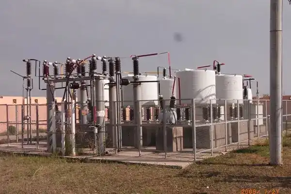
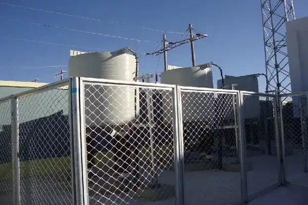
To keep the grid stable and protect expensive infrastructure, it is important to install 10kV outdoor line compensation equipment the right way. This method adds reactive power to balance out magnetic loads with capacitive power. This raises the power factor above 0.95 and keeps the voltage stable across long-distance transmission lines. To put something correctly, you need to carefully look at the site, follow IEC and IEEE standards, use the right grounding methods, and try everything thoroughly before turning it on. When used safely, these systems cut technical costs by 15–30%, keep tools from breaking down, and make sure they work reliably for decades, even in harsh weather.
 |
 |
Understanding 10kV Outdoor Line Compensation Equipment
Voltage drops at line ends, too much reactive power use, and fines for bad power factor are all problems that modern power distribution networks have to deal with all the time. These problems can be fixed by carefully placing capacitor banks straight onto overhead power lines instead of putting them all in one place at substations.
Core Components and Working Principles
Core components include capacitor banks that dynamically supply reactive power, using low-loss all-film dielectric capacitors (<0.2 W/kvar) with stable performance across temperatures. Series reactors (6% or 13%) suppress fifth and seventh harmonics. Vacuum contactors or thyristor switches apply zero-crossing control to reduce inrush current. Smart controllers monitor three-phase voltage/current for millisecond switching decisions, while protection systems guard against over/undervoltage, overcurrent, and phase imbalance.
Measurable Benefits for Operations
Supporting voltage is especially helpful for remote feeds that are farther than 10 kilometres away, where line impedance causes big drops in voltage. By adding capacitive reactive power at key locations—usually every two-thirds of the way along the feeder—these systems raise the voltage at the terminals back to levels that meet utility standards. By getting rid of the power factor fees that utility companies put on sites that run below 0.90 power factor, manufacturing plants that use a lot of motors can cut costs right away.
Gains in energy saving lead straight to higher profits. I²R resistance losses are cut in the same way when the flow of reactive current through transmission lines is cut. Increasing the power factor from 0.75 to 0.95 can cut distribution costs by 20 to 25 percent, which can save a lot of money every year for multi-megawatt businesses. Cleaner power transfer to sensitive computers is good for data centers, and hospitals make sure that life-critical equipment keeps running.
Application Scenarios Across Industries
Along long country feeders that serve farming areas with seasonal irrigation loads, distribution system workers put up pole-mounted 10kV outdoor line compensation equipment. The system's multi-step switching can quickly adjust to changes in load, keeping the voltage safe during times of low demand and overvoltage during times of high demand. These devices are put in place by urban utility networks to keep business areas from going dark during afternoon peak loads, which happen when air conditioners put a lot of stress on the grid.
In industries like steel mills, mines, and petrochemical plants, where big induction motors cause a lot of lagging power factor, they are used. Adding renewable energy poses its own problems. For example, wind farms and solar panels produce power at irregular times, which makes the voltage on the grid less stable. Dynamic reaction is provided by compensation equipment, which smooths out changes in voltage and supports grid codes that require certain reactive power inputs from generation facilities.
Pre-Installation Considerations for Safe Setup
Preparing well helps keep mistakes and safety issues from happening. Installations that go smoothly start months before the equipment arrives, with careful planning that takes into account technical, environmental, and legal factors.
Site Assessment and Environmental Analysis
Conditions at the spot affect how long 10kV outdoor line compensation equipment lasts and how well it works. Coastal sites need better protection against rust. Enclosures made of stainless steel 304 and insulated with silicone rubber don't break down when exposed to salt mist. Extreme temperature changes must be taken into account in desert settings. Industrial-grade units work effectively from -40°C to +55°C, but installers must check that the mounting hardware allows for thermal expansion.
Testing the soil's resistance helps with designing the grounding. To reach the 4-ohm resistance goal for successful fault clearing, high-resistance soils might need chemical cleaning or bigger grounding grids. In places where there is a lot of seismic action, mounting structures need to be stronger and follow local building rules. When you're above 1,000 meters, you need to lower or raise the BIL (Basic Impulse Insulation Level) rates for installations to make up for the lower dielectric strength in the thinner air. Engineers look at demand trends from the past to find out how much reactive power is needed at its peak and how the voltage drops along the line. Overcapacity can lead to a dangerous leading power factor when loads are small, and undercapacity doesn't do what it's supposed to do. Load flow studies that use software to simulate different situations help to confirm design choices before they are bought.
Equipment Selection and Technical Specifications
Outdoor pole-mounted equipment offers flexible, lower-cost deployment along distribution lines, while indoor substations provide controlled conditions but require more space and civil works. Selection must match grid requirements, including voltage ratings (e.g., 10–12 kV systems), capacitor bank sizes (150 kvar–multi Mvar), and switchgear fault levels (20–31.5 kA). Compliance with IEC 60871, IEEE standards, and UL listing is required, with factory testing such as PD, impulse, and 10,000-cycle endurance verification.
Regulatory Compliance and Permitting
Agreements between utilities that connect them set technical standards and approval processes. In many places, planned compensation needs to be backed up by technical studies that show it won't hurt the security of the grid or the customers nearby. Protection coordination studies make sure that new equipment works well with current overcurrent protection systems and keeps its sensitivity when there is a fault. In the US, Article 460 of the National Electrical Code (NEC) controls how capacitors are installed. It says how to protect against overcurrent, how to disconnect the capacitor, and how big the conductors must be. Changes made at the local level may add more standards. In places with strict land use rules, building permits are often needed even for outdoor pieces that are placed on poles. In sensitive ecological places or near rivers, you may need an environmental permit. The paperwork for safety plans should talk about arc flash dangers, including how much energy an event can produce and what safety gear is needed for maintenance work. Lockout-tagout processes and confined space measures are required by OSHA rules when they apply. Making site-specific safety plans before mobilisation shows that you care about worker safety and makes the project run more smoothly.
Step-by-Step Guide to Installing 10kV Outdoor Line Compensation Equipment Safely
The right way to put something keeps people safe, keeps tools from breaking, and makes sure it works well for a long time. Each step needs close attention to detail and strict obedience to safety rules.
Risk Assessment and Safety Planning
A full job hazard analysis identifies electrical, mechanical, and environmental risks in medium-voltage systems, including stored capacitor energy and induced voltages. Safe work requires isolation, lockout/tagout, verification, and temporary grounding. High arc-rated PPE (≥40 cal/cm²), insulated gloves, and protective gear are essential. Confined space precautions, calibrated torque tools, voltage monitoring, and rated grounding systems ensure safe installation and maintenance.
Installation Techniques and Best Practices
10kV outdoor line compensation equipment mounting structures have to be able to handle mechanical pressures caused by things like the weight of the equipment, wind, earthquakes, and ice buildup. For pole-mounted systems, hot-dip galvanised tubular steel or formed channel frames are usually used to keep them from rusting. When designing a foundation, the frost depth and earth bearing ability are taken into account. To avoid yearly heaving, concrete piers are pushed below the frost lines. Anchor bolt embedment depth and torque specs are based on estimates made by structure engineers, not guesses.
Grounding sets the reference potential and offers ways for fault currents to return. All metal containers are linked to the grounding electrode system by equipment grounding wires that are the right size according to NEC Table 250.122 and are based on the upstream overcurrent device ratings. Separately derived systems need links for grounded conductors that meet the requirements of NEC 250.30. The design of the ground grid tries to keep the highest touch and step potentials within safe limits during faults. In public places, this means that the potentials should be less than 50 volts. Electrical ties need to be carefully made. To prepare a conductor, you have to cut out specific lengths of insulation without damaging the conductors below. To brighten metal and get rid of rust that makes it more resistant, contact areas need to be cleaned. Connector application must exactly follow the torque specs given by the maker. Power tools with measured torque settings make sure that this happens every time. After the joints are tightened, they are checked to make sure they seat properly and there is no damage to the strands.
Testing and Commissioning Procedures
Pre-energization testing verifies installation integrity before applying voltage. Insulation resistance tests (typically ≥1000 MΩ) detect moisture, damage, or contamination. Capacitor bank capacitance must stay within ±5%, while loss tangent indicates dielectric aging. Protection relays, interlocks, and transformer ratios are functionally tested via simulated faults. Energization is staged with visual checks and live monitoring, followed by full documentation including test records, as-builts, and commissioning reports.
Maintenance and Troubleshooting for Long-Term Safety and Performance
Regular repair makes things last longer and stops them from breaking down without warning, which can cause big problems and cost a lot of money. 10kV outdoor line compensation equipment that is well taken care of last 20 to 25 years, while units that aren't kept break down early.
Routine Maintenance Activities
Visual checks done every three months find problems before they get bad enough to cause crashes. Technicians check casings for rust and make sure that gasket seals stay in place so that the equipment stays dry. The outside of the insulator shouldn't have any salt buildup, industrial pollutants, or biological growth that could allow leaks to happen. Managing vegetation keeps branches from touching electrical parts or stopping airflow, which is important for controlling temperature. Unusual temperature spikes found by thermal imaging scans can mean that connections are loose or parts are breaking down. Differences in temperature of more than 10°C between similar parts should be looked into. Hot spots at connection places show that the mechanical parts are free and need to be re-torqued. When capacitor cans show high temperatures, the internal elements may fail, which means they need to be replaced before they completely break down. Specialised testing methods are used to check the health of capacitors. Capacitance and dissipation factor data show how things change slowly over many years of use. Sudden changes mean there are issues; long-term patterns allow for planned replacements before failures stop service. Some more advanced systems have online tracking that checks the parameters of the capacitor all the time and sends real-time alerts when numbers change outside of allowed ranges.
Common Issues and Troubleshooting Strategies
Vacuum switch maintenance is typically required every five years for devices with ~1,000 operations annually, using contact erosion data and X-ray inspection to detect internal wear or contamination. Voltage instability may indicate compensation, sensor, or control faults. Audible noise, capacitor bulging, dielectric leaks, insulation tracking, and harmonic resonance all signal failures requiring immediate action. Power quality analysis helps identify frequencies and guide retuning or filtering.
Professional Support and OEM Engagement
Complex problems are beyond the skills of most repair staff, so they need expert help from the maker. OEMs know a lot about how technology works, why it breaks down, and how to fix it because they've done thousands of setups. Many makers let you do remote diagnostics through SCADA connection. This lets you look at working data to find problems without having to go to the site. Warranty coverage protects you financially against mistakes that happen too soon. Standard guarantees usually cover production flaws for 18 to 24 months after the product is put into use. They do not cover damage caused by wrong use, poor upkeep, or outside events. For an extra fee, extended warranty plans offer longer coverage periods, which are useful for important setups where downtime can have very bad effects. Service agreements make ongoing ties of help official. Technicians who are taught by the manufacturer do regular checks, tests, and adjustments as part of annual maintenance contracts. Priority emergency reaction clauses make sure that people are quickly mobilised when power goes out without warning. Parts stocking deals make sure that important new parts are always available, so there aren't long downtimes while you wait to get old parts.
Comparative Insights and Best Practices in Reactive Power Management
Making smart choices about 10kV outdoor line compensation technology, parts, and providers has a direct effect on the success of a project. Procurement experts can find the best options by understanding the key differences.
Outdoor Versus Indoor Installation Trade-offs
Outdoor pole-mounted designs are most common in country utility uses because they are very flexible and cost-effective. Getting rid of building construction cuts capital costs by a large amount and allows placement exactly where pay brings in the most money. Modular designs allow for small increases in capacity as load increases. This way, you don't have to spend too much money up front on capacity that you won't use. Accessibility for maintenance work can be hard at times; to reach high installations, you may need to use bucket trucks or climbing gear. Installing a substation indoors keeps the equipment safe from harsh weather and disease by creating a controlled environment. Controlling the temperature stops thermal cycle, which puts stress on parts. Vandalism and unauthorized entry can't happen because of security steps. In crowded cities, where space is limited, indoor choices may be limited. On the other hand, greenfield projects can build substations that can accommodate expected future equipment adds. The choice depends on the needs of the application, the limitations of the place, and a study of the total cost of ownership.
Component Performance Characteristics
Component performance depends on technology choice. Polypropylene film capacitors offer low dissipation (<0.2 W/kvar), self-healing capability, and long-term capacitance stability. Reactor design affects filtering and losses: iron-core types are compact but have hysteresis losses, while air-core designs avoid core losses but are larger. Switching options vary—vacuum contactors are durable, thyristors enable stepless control but add losses, and mechanical switches are cheaper but require more maintenance.
Supplier Evaluation and Procurement Excellence
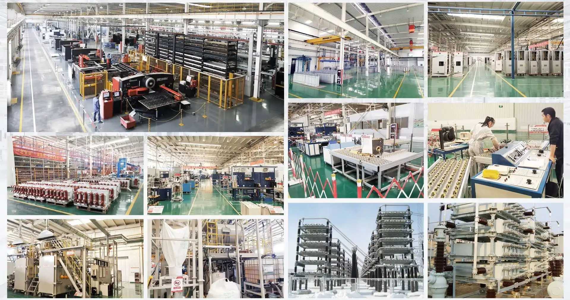
Supplier evaluation and procurement excellence depend on warranty strength, delivery reliability, and technical support. Standard warranties are typically 18 months from commissioning, while 36–60 months indicates higher confidence; terms should clearly define coverage, exclusions, and claims. Local inventory enables faster fulfillment, while just-in-time delivery improves cost efficiency. Strong vendors also provide application engineering, commissioning support, and responsive after-sales service for complex projects.
Conclusion
Installing 10kV outdoor line compensation equipment safely protects workers, makes sure that rules are followed, and sets the stage for years of effective operation. The process needs careful planning that takes into account the site's conditions, the equipment's specs, and safety rules. Problems can be avoided by carefully fixing, wiring, and connecting the electrical parts. Thorough testing confirms that the equipment is ready for use. Regular maintenance keeps things running smoothly and finds problems before they become major problems. Working with experienced equipment providers gives you access to tried-and-true designs, technical know-how, and support tools that make projects more successful while keeping risk under control throughout the lifecycles of the equipment.
FAQ
1.What Safety Precautions Are Essential During Installation?
Setting up electrically safe working conditions is the most basic safety requirement. This says that acceptable voltage detection must be used to make sure that circuits are turned off, lockout-tagout must be used to keep them from being turned on again, and temporary safety grounds must be put in place. Arc-rated PPE keeps you safe from flash dangers when you're working with electricity. When working on platforms or poles above six feet high, fall safety is required. Extreme temperatures, confined areas, or dangerous atmospheres are all examples of environmental hazards that need control measures that are specific to the place.
2.How Often Should Maintenance Be Performed?
Visual checks every three months find problems right away, like insulators that are broken, connections that are rusted, or external contamination. Thermal imaging, electrical testing of capacitors and protection systems, and mechanical checking of switching devices are all parts of the annual thorough maintenance. Installations that are used a lot should be checked every six months. Online tracking systems lower the number of inspections needed by keeping an eye on parameters all the time. This lets condition-based maintenance happen instead of fixed-interval plans. Manufacturer's suggestions in equipment guides are basic guidelines that can be changed depending on how bad the working environment is and how important the application is.
3.Do These Systems Effectively Reduce Energy Losses?
How much loss reduction is possible relies on the system's starting power factor and how it is set up. When a facility raises its power factor from 0.75 to 0.95, it usually cuts distribution system losses by 15 to 25 percent. When voltage support adjustment is added to rural feeders, the smaller amount of power that flows through line impedances saves even more money. Cost savings are closely linked to higher energy efficiency, and the payback times are often less than three years. In addition to saving energy, not having to pay a penalty for low power factor means that industrial and business users whose utility bills include power factor charges will immediately see their monthly costs go down.
Partner with Xi'an Xikai for Reliable Compensation Solutions
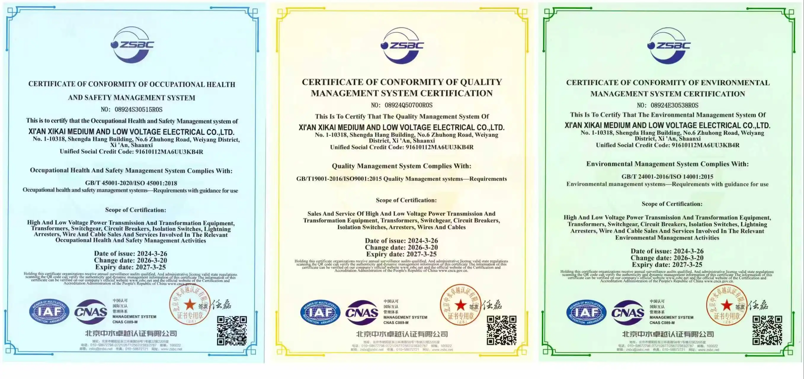
Xi'an Xikai Medium & Low Voltage Electric Co., Ltd. has a lot of experience making high-quality equipment for compensating reactive power that is accepted by many different businesses. As a reliable 10kV outdoor line compensation supplier, we provide capacitor banks, reactors, and full pole-mounted compensation systems that are made to work in tough outdoor conditions. Products are tested thoroughly and come with long warranties that cover more problems. They also meet strict IEC and IEEE standards. We offer expert advice to help you find the best solutions for your grid needs, whether they are for utility distribution networks, industrial facilities, or projects that integrate green energy. Contact our team at serina@xaxd-electric.com, amber@xaxd-electric.com, or luna@xaxd-electric.com to discuss your compensation equipment needs with experienced professionals. As a leading compensation equipment manufacturer, we deliver customized systems, competitive pricing on volume orders, and responsive after-sale support ensuring your investment delivers lasting value.
References
1. Institute of Electrical and Electronics Engineers (2014). IEEE Recommended Practice for Reactive Power Compensation in Industrial and Commercial Power Systems. IEEE Standard 1036.
2. International Electrotechnical Commission (2019). Shunt Capacitors for Power Systems - Part 1: General Performance, Testing and Rating. IEC 60871-1.
3. National Fire Protection Association (2023). National Electrical Code, Article 460: Capacitors. NFPA 70.
4. Smith, J.R. and Thompson, M.K. (2021). Medium Voltage Power Distribution and Safety Practices. Electrical Engineering Press.
5. Anderson, P.M. and Fouad, A.A. (2020). Power System Control and Stability, Third Edition. Wiley-IEEE Press.
6. Electric Power Research Institute (2018). Application Guide for Shunt Capacitor Banks on Distribution Systems. EPRI Technical Report 3002013910.