Why Use a 10kV High Volatge Reactive Power Compensation Device?
2026-11-06 17:35:13
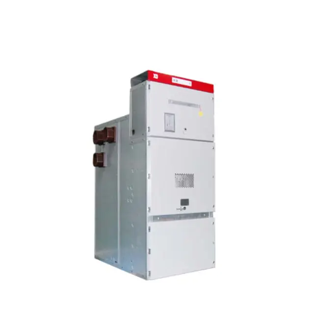
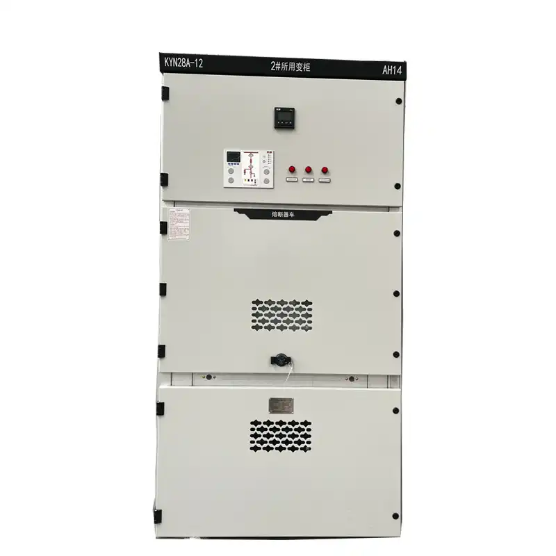
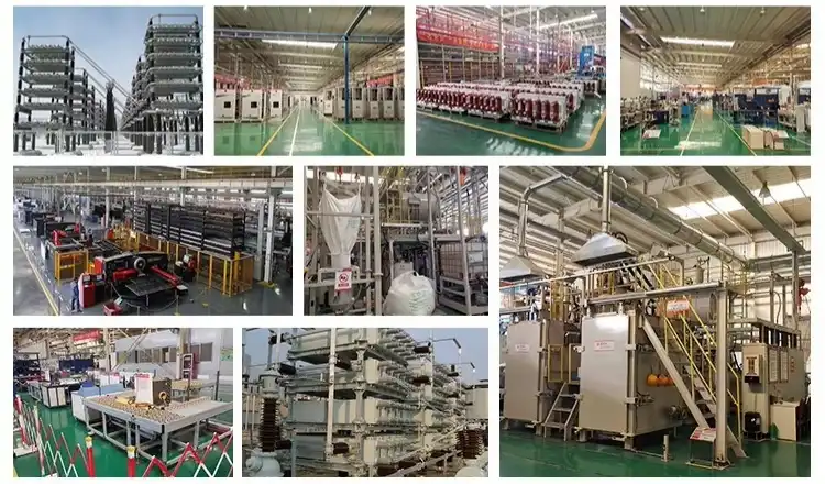
A 10kv high volatge reactive power compensation device provides plants and utilities a direct approach to reduce wasted current on medium voltage networks. It returns reactive power to the grid, which is used by motors, transformers, furnaces and compressors. This means the grid has less non-productive current to carry. The outcome is a greater power factor, reduced line losses, steadier voltage and more useable transformer and feeder capacity. Compensation may also assist avoid the fines for low power factor that many utilities implement. Actual savings depend on load data, tariffs and network circumstances, hence we always urge engineering confirmation before purchase. This page describes how the equipment works, where it fits and how to pick it. This is a question that buyers often ask about what a 10kv high voltage reactive power compensation device accomplishes in a network, so let’s start with the fundamentals. A 10kV high-voltage reactive power compensation device is medium voltage equipment connected to 6kV, 10kV or similar distribution system that manages reactive power Typical designs include fixed or automated capacitor banks, detuned capacitor systems, static var compensators (SVCs), static var generators (SVGs) and hybrid designs. A comprehensive system may have capacitors, switchgear, reactors, controllers, protective devices and monitoring features. Their frequent areas include substations, workshops, mines and green energy plants. In China, the automated capacitor type is typically termed a TBB cabinet. So the first step is to link the technology to the network, not a catalog number. The reason is that each arrangement responds differently to variations in load and harmonics. Active power (kW) conducts meaningful work . Motors and transformers need magnetic fields. They are generated from reactive power (kvar). Power factor is kW divided by apparent power (kVA) which is the load on the wires and transformers as a whole. A load of 0.80 power factor requires 1,250 kVA to provide 1,000 kW. If you raise the power factor to 0.95, the same 1,000 kW would now need roughly 1,053 kVA. Because current follows perceived power, the line carries around 16% less current with the same actual load. Then line losses are reduced by roughly 29% since they are proportional to the square of the current. These figures illustrate the advantage of utilizing a high-voltage reactive power compensation device of 10kV on previously loaded feeders. The capacitor banks provide leading reactive power to offset the lagging reactive power of inductive loads. An automated controller examines the voltage, current, and power factor and then switches the compensation stages on or off as demand varies. An SVG may add precisely regulated current via power electronic converters so they can closely follow changes in the load that are quick or not balanced. SVCs are used to link thyristor-controlled reactors to capacitor branches so as to provide smooth changes when the capacity is high. The least expensive automated capacitor banks function best with steady inductive loads. Alternatively, rapidly changing or non-linear loads may need SVG, SVC or combination thereof. Therefore, the proper combination of cost and performance relies on the behavior of the load. Thus, every 10kV high-voltage reactive power compensation device should be based on the load data. In almost every project we look at, we see three strong reasons to put in a 10kV high voltage reactive power compensation device. First, it functions better. It performs no practical work but reactive current warms up wires, busbars and transformer windings. When the 10kV high-voltage reactive power adjustment device provides that reactive power near to the load, the upstream network has less current, which implies reduced I²R losses and cooler equipment. The previous example showed roughly 16% less current and about 29% fewer line losses for the same actual power. The TBB10 by itself monitors reaction power and strives to maintain the power factor at 0.95 or greater. Each site has different rates, hours of operation, and network impedance so any savings amount is just that – a guess until we can confirm with tests. For the second reason, there is enough space. Limits in kVA are set for transformers and feeders, and reactive current uses some of that limit. In the first case, raising the power factor from 0.80 to 0.95 frees up about 197 kVA of a demand for 1,250 kVA, or about 16%. A factory that wants to add new production lines may add load to a transformer before upgrading it. A steady power factor can lower these costs because many companies also charge for changes in power factor or demand. The rules for rates are different for each utility, so buyers should look at their own tariff schedules. A 10kv high volatge reactive power compensation device is not a replacement for a capacity study, but it is often a good first step. Stable voltage is the third reason. A lot of reactive current is drawn by big motors, compressors, and furnaces. This can lower the voltage on long 10kV feeders. Providing reactive power in the area helps keep the voltage profile stable and reduces sags and swells. With sensors, the TBB10 checks voltage and current in real time, and in less than 20 ms, its controller turns on capacitor banks. It can keep up with sudden changes in load in many industrial settings thanks to its speed. When you choose, we make it clear that an SVG or SVC may be better for loads with a lot of flicker, like arc furnaces. Any 10kV high-voltage reactive power compensation device should match reaction speed to the real load, not to the biggest number on the datasheet. The TBB10 is our 10kV high-voltage reactive power compensation device for 6–10kV systems, and it uses the concepts discussed above. It is applicable to 6-10kV, 50Hz power systems. It operates at temperatures ranging from -25°C to +45°C and has a capacity of 100 to 10,000kVar. The CPU modulates the reactive power according to a real time grid demand to minimize the voltage fluctuation and energy loss. Before ordering, consumers should verify that the 50Hz rate is the frequency of their system. This is because compensating equipment must be compatible with the network to which it is connected. Customers are also required to provide us with a single-line schematic, short-circuit level and load profile. This enables our engineers to validate the capacity and protection settings against real-world situations as opposed to the assumptions in the nameplate. The TBB10 has three reactor types to choose from to safeguard capacitors and the network. When the capacitor stages are energized, a reactor with a reactance of 0.1 to 1% stops the inrush current. A 6% reactance reactor is used to eliminate 5th and higher harmonics which are typically generated by motors and converters. The 12% reactance reactor is intended to be used for the third and higher harmonics. Choose the incorrect reactance and you may force a capacitor bank into harmonic magnification. You should utilize a harmonic measurement to assist you choose a reactance. This check will be conducted on any 10kV high voltage reactive power compensation device connected to a bus that contains drives or converters. IEEE Std 519 establishes harmonic limitations at the point of common coupling. This provides purchasers with defined objectives for power quality. When clients measure harmonic content we can assist them choose the optimal reactor. The TBB10 is a 10kV high voltage reactive power compensation device, and is designed modularly so that the capacity may be increased without system down time. Self diagnostic alerts & IoT based remote monitoring let operators examine the condition of each cabinet without visiting any of them. This is useful for utilities and plants that have geographically dispersed installations. Arc-resistant enclosures make the unit safer. The unit can operate in high-dust conditions and within a temperature range of -25°C to +45°C. Parts are evaluated for dielectric strength and thermal cycling and production is done according to ISO 9001. Compliance with IEC 60871 and IEEE 18 has been verified. Regularly examine alarms, temperatures, condition of capacitors, fuses, reactors and cable terminations. For outdoor installs, speak to us about enclosure and environmental protection requirements early on, since customers often have concerns about the reliability of the controller outdoors. The best approach to choose a 10kV high voltage reactive power compensation device is to measure the load. First determine the active power, the current power factor and the required power factor. Then determine the desired power factor by Qc = P(tanφ1 − tanφ2). 421 kvar is the answer. If a 1,000 kW load changes from 0.80 to 0.95, the required capacity is 421 kvar. Write down the load profile, the harmonic spectrum, the change of the voltage and the plans for expansion for a whole operational cycle. Automatic capacitor banks, such as the TBB10, are usually the least expensive option for reliable inductive loads. SVGs are able to react fast and correctly to changing, not linear or not balanced loads but often cost more and need more care. SVC’s are suitable for heavy duty, but may need more room and better filter engineering. When sizing a 10kv high volatge reactive power compensation device, a harmonic analysis and a check for harmonic magnification on the network should be carried out. In industries motors, pumps, compressors, elevators and transformers all need to be adjusted. Mines include dust, lengthy feeds, hoists, crushers, and restricted entrance for maintenance, so being able to monitor from a distance helps. In substations the TBB10 is used to maintain voltage steady against harmonics and erratic output from green generators. It may be utilized for retrofitting existing systems in hospitals and malls. Xi'an Xikai's plateau equipment can operate at an altitude of 4,000 meters. Our products are employed in state grid systems, steel and metallurgy, petrochemicals, rail transportation and renewable energy projects. In certain applications where the reactive power fluctuates rapidly , such arc furnaces and welding , you may also require an SVG or SVC along with a capacitor based setup . Each 10kV high voltage reactive power compensation device should be built for a specific application. The price depends on the kind of reactor, capacity, switchgear, enclosure, automation, testing and support. That’s why we don’t quote you a price until we know more about the job. A bid should include what equipment is included and what is excluded, factory testing, packing, commissioning, training, replacement parts, guarantee and shipping conditions. International purchasers should know whether Incoterms apply, delivery dates, paperwork and local service arrangements. Utility procurement teams also verify vendors are competent and have expertise with the grid. Check during commissioning interlocks, grounding, phase sequence, CT and VT polarity and interlocks. Then put down typical power-quality values so that you may compare findings later on. Xi'an Xikai has more than 25 years of expertise, distinctive design and professional service 24 hours a day, seven days a week. " When assessing any 10kV high voltage reactive power compensation device, look at the whole package, not just the unit price. A 10kv high volatge reactive power compensation device balances out the reactive demand of motors, transformers, and furnaces. This lowers current, reduces line losses, supports voltage, and frees up transformer and feeder capacity. Going from 0.80 to 0.95 in power factor cuts current by about 16% and needs 421 kvar for a 1,000 kW load, as shown in the working case. Capacitor banks work best with steady loads, while SVGs and SVCs work best with loads that change quickly or are not straight. Measured data on load, harmonics, and voltage should be used to make the choice. The TBB10 works with systems from 6 to 10kV at 50Hz and 100 to 10,000kVar at room temperature. It has different reactor options for inrush, 5th-plus, and 3rd-plus harmonics. Because savings vary from site to site, a good purchase starts with engineering validation, a clear quote scope, and documented testing. It provides leading reactive power to compensate for the lagging reactive power requirement of motors, transformers and other inductive loads. This may minimise current and line losses, so freeing up transformer and feeder capacity and supporting voltage stability. Use the observed active power, existing power factor and goal power factor in the calculation . Qc= P(tanφ1-tanφ2) . For example, a load of 1000 kW changing from 0.80 to 0.95 power factor would take roughly 421 kvar. Site load and harmonic measurements were used to ensure final sizing. Automatic capacitor banks are usually ideal for fairly constant inductive loads. SVCs are utilised for the large capacity applications which need smooth reactive power regulation whereas SVGs are suited for the unbalanced, unchanging and nonlinear loads and may react faster. The decision should be based on real load behaviour and harmonic circumstances. The TBB10 is a 10kv high volatge reactive power compensation device made by Xi'an Xikai, which also offers customized engineering, ISO 9001 production, and expert support 24 hours a day, seven days a week. We've worked on projects across State Grid systems during our more than 25 years of experience. Send serina@xaxd-electric.com, amber@xaxd-electric.com, or luna@xaxd-electric.com your system voltage, capacity goal, load data, and site conditions, and someone from our team will get back to you with a setup suggestion. If you want to know more, go to xaxd-electric.com. 1. IEC 60871-1: Shunt Capacitors for AC Power Systems Having a Rated Voltage Above 1000 V, Part 1: General (2014) 2. IEEE Std 18: IEEE Standard for Shunt Power Capacitors (2012) 3. IEEE Std 519: IEEE Standard for Harmonic Control in Electric Power Systems (2022) 4. IEEE Std 1036: IEEE Guide for Application of Shunt Power Capacitors (2010) 5. Understanding FACTS: Concepts and Technology of Flexible AC Transmission Systems (1999) 6. Power System Stability and Control (1994)What Is a 10kV High-Voltage Reactive Power Compensation Device?
Definition and Typical Configurations
Power Factor and Reactive Power
How Capacitor Banks, SVGs, and SVCs Work
Three Reasons to Use a 10kV High-Voltage Reactive Power Compensation Device
Lower Current and Lower Losses
Released Capacity and Fewer Penalties
Voltage Support and Response Speed
TBB10 High Voltage Reactive Power Automatic Compensation Device
Rated Specifications
Reactor Options for Inrush and Harmonics
Build Quality, Monitoring, and Maintenance
Selecting, Applying, and Buying a 10kV Compensation System
Size the System and Compare Technologies
Applications Across Industry and Utilities
Quotation Scope, Cost, and Support
Conclusion
FAQ
1. What does a 10kV high-voltage reactive power compensation device do?
2. How do I determine the required compensation capacity?
3. When should I choose a capacitor bank, SVG, or SVC?
Request a 10kV High-Voltage Reactive Power Compensation Solution from Xi'an Xikai

References